Technical
Radar Antenna Selection: Horn, Lens, Drop and Air-Purge for Dust, Steam and Condensation
Horn, lens, drop and air-purge radar antennas compared for dusty, steamy and condensing tanks and silos — get the right radar antenna from WELK.
Horn, lens, drop and air-purge radar antennas compared for dusty, steamy and condensing tanks and silos — get the right radar antenna from WELK.
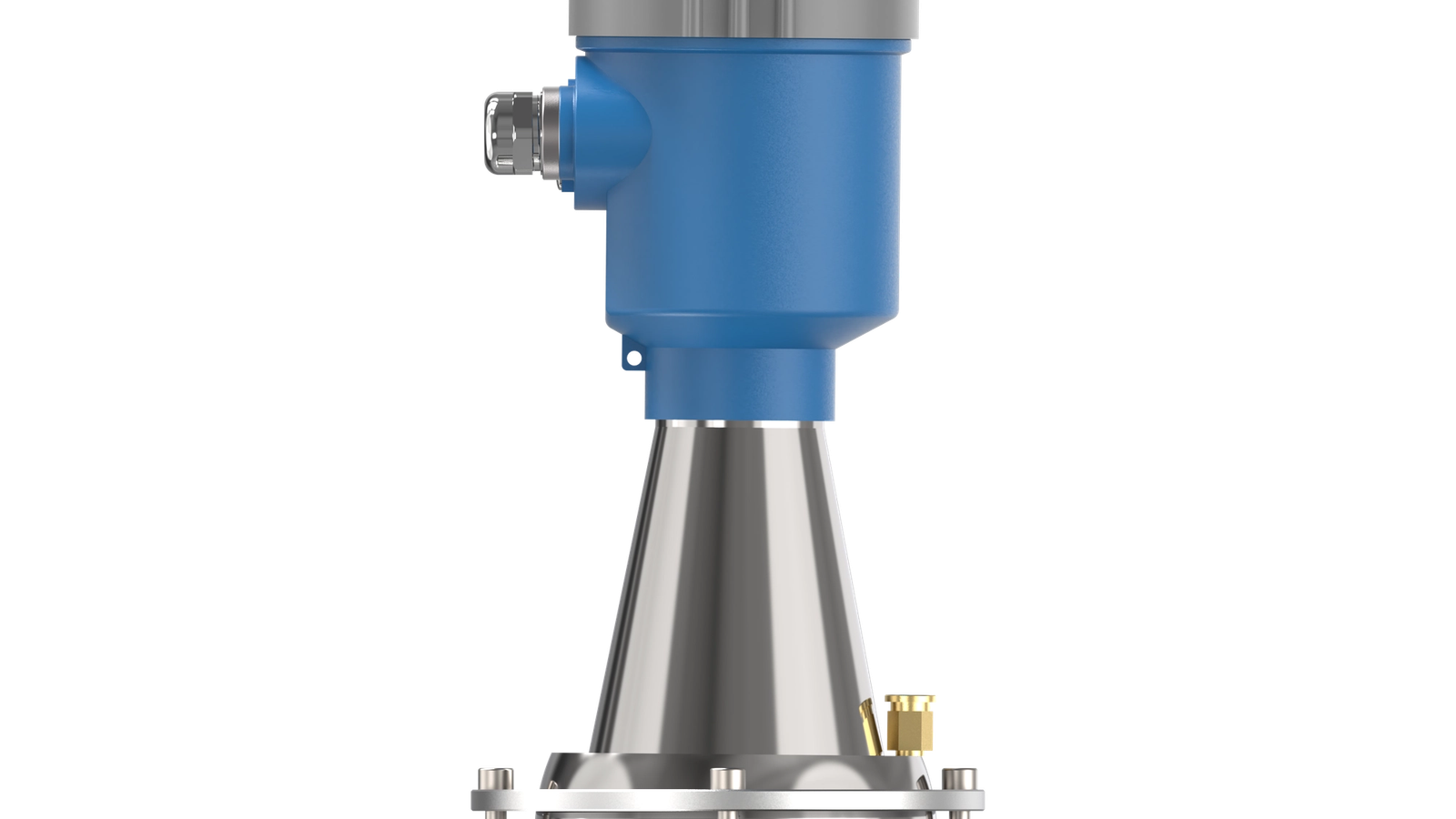
A radar level transmitter antenna is the physical aperture that launches and receives the microwave signal a level transmitter uses to measure the distance to a product surface. In a modern 80 GHz FMCW (frequency-modulated continuous wave) radar level meter, the antenna determines how tightly the beam is focused, how much energy reaches the target and how the instrument copes with dust, steam, condensation and build-up — which is why the same electronics can deliver ±2 mm accuracy and up to 120 m of measuring range in one installation and fail in another. The antenna is not an accessory; it is the single most influential component in the measurement loop. This guide compares the four antenna families used on industrial radar level transmitters — horn, lens, drop/rod and air-purge variants — and explains how to select the right one for tanks and silos in chemical, cement, water and food plants. For a closer look at what modern 80 GHz instruments can actually measure, our engineers explain the accuracy story in detail in how accurate an 80 GHz radar level meter is.
Two transmitters with identical electronics and identical software will measure completely differently if their antennas differ. The antenna controls three things that decide whether a level reading is stable, repeatable and trustworthy.
Signal focusing. Radar energy spreads out as it leaves the antenna, and the angle of that spread — the beam angle — is set almost entirely by the aperture size relative to the wavelength. At 80 GHz the wavelength is only 3.75 mm, so a small antenna can produce a tight beam that older 6 GHz and 26 GHz radars needed a much larger horn to achieve. A focused beam keeps the energy on the product surface instead of bouncing off the tank wall, internal structures, manways or ladders, which produce false echoes that the software must reject.
Beam angle. Narrow beams, typically 3–8° depending on antenna style, matter most in three situations: tall, narrow silos where the wall is close to the beam; tanks with agitators, heat exchangers or baffles that would create parasitic reflections; and small nozzles where the antenna must fit through a restricted opening without the beam clipping the nozzle wall. A beam that clips the nozzle loses energy and generates a strong echo from the nozzle itself. At 80 GHz, a 3° beam angle concentrates most of the energy into a spot roughly 0.5 m wide at 10 m distance, compared with several metres for a wide-beam low-frequency instrument.
Resistance to condensation, dust and build-up. Every antenna eventually collects condensation, dust or product on its face. How much that layer degrades the measurement depends on the antenna's geometry and materials. Flush or gently sloped surfaces shed liquid; deep cavities trap it; purge connections remove it actively. A coating on the antenna face can attenuate the signal, scatter it or shift the measured distance slightly — so antennas that shed or actively clean their own surface are worth far more than their modest price difference in wet or dusty service.
The practical consequence: antenna selection should happen before nozzle size is fixed on the tank drawing, not after the flange is welded in place. The nozzle diameter, process connection and process conditions you specify determine which antenna styles are physically possible, and that decision cascades into accuracy, reliability and maintenance cost for the life of the instrument.
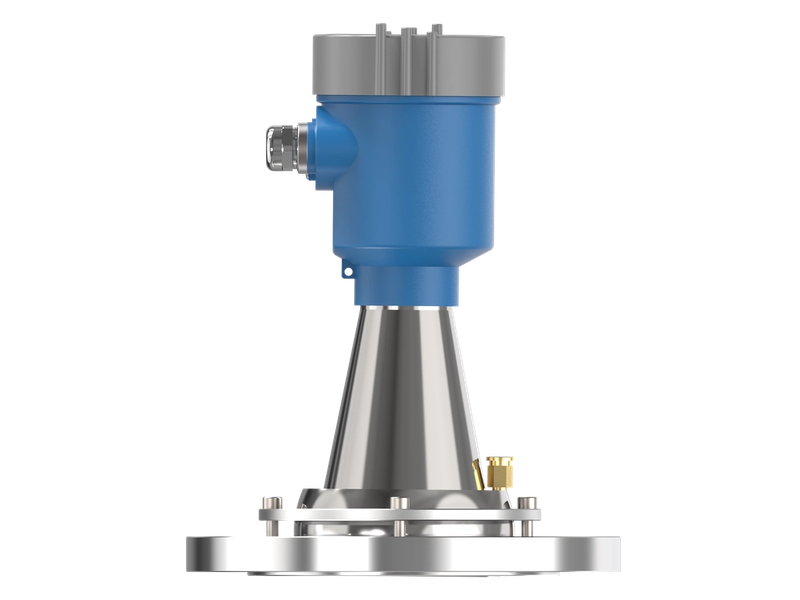
The horn is the default antenna for general-purpose radar level measurement, and for good reason: it is robust, simple, inexpensive and available in a wide range of sizes and materials. Horns are hollow metal cones or parabolas that guide microwave energy from the electronics into the vessel. They come in two main geometries.
Conical (cone) horns. The classic straight-sided cone is the standard fitment on most radar level transmitters. It offers a good balance of beam angle, size and cost, with typical beam angles from 8° down to about 4°, depending on horn length and diameter. Conical horns suit the majority of storage tanks, process vessels and intermediate-level applications where the nozzle is large enough to accept them. They are available in a range of process connections, most commonly DN80/DN100 flanges and 3-inch or 4-inch threaded mounts, and they can be supplied in PTFE-lined or all-metal versions for chemical service.
Parabolic horns. A parabolic (dished) horn uses a curved reflecting surface to produce a much narrower beam than a conical horn of the same diameter, often down to 3–4°. The tighter beam gives higher signal strength at long range and better immunity to internal obstructions. The trade-off is size and cost: parabolic horns are larger, heavier and more expensive, and they generally need a bigger nozzle. Use a parabolic horn when you need maximum range in a large tank or silo, or when internal structures force you to keep the beam well away from the walls. The main 80 GHz radar level meter range from WELK includes both conical and parabolic horn options so the same electronics can be matched to the right aperture for each tank.
When a horn is the wrong choice. Horns have two weaknesses. First, they protrude into the vessel, so in a short nozzle or a tank with a low roof, a long horn may not fit. Second, the open cone interior can collect condensation or product, especially when the vessel is pressurised and steam is present. If the nozzle is small, the roof clearance is tight, or the process is wet, one of the antenna families below will usually serve better.
Lens antennas were developed to solve a specific contradiction: process engineers wanted narrow, well-focused beams, but modern 80 GHz radars are small enough that users increasingly demand small nozzles — and a conventional horn cannot produce a tight beam through a 40 mm or 50 mm nozzle.
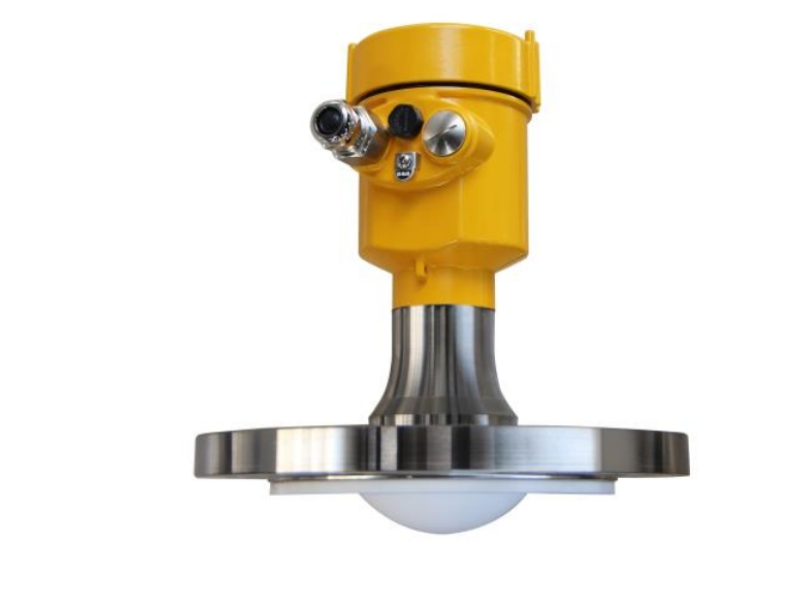
A lens antenna uses a dielectric lens, normally PTFE, moulded across the face of the antenna to focus the beam the way an optical lens focuses light. Because the lens fills the nozzle opening completely, the antenna has a smooth, sealed face that is easy to clean, and the focusing effect lets a small-diameter antenna achieve a beam angle of only 3–4°. The lens also physically separates the antenna interior from the process, which protects the electronics from condensation and corrosion.
Lens antennas are the best choice for:
The main limitation is chemical and mechanical robustness. PTFE lenses are resistant to most chemicals, but they can be damaged by abrasive slurries or by physical impact, and their temperature rating is lower than an all-metal horn. For most tank and silo applications, however, the lens antenna offers the best combination of small footprint, tight beam and cleanability, which is why it is the standard choice on modern 80 GHz instruments.
Drop antennas, also called rod or stub antennas, are short, slim antenna elements that extend just a few centimetres into the vessel. They are essentially a compromise for installations where neither a horn nor a lens will fit: very small nozzles, very limited roof clearance, or plastic and lined tanks where the antenna must be short.
A rod antenna trades beam focus for compactness. Its beam angle is wider than a lens or horn of the same nominal size, which means it is best used in tanks with generous free space above the product and few internal obstructions. Where those conditions hold, the drop antenna is perfectly adequate for standard level measurement, and its low profile makes it nearly immune to condensation pooling on the antenna face.
Drop antennas are commonly used in:
The selection rule is straightforward: if you have room for a horn, use a horn; if you have only a small nozzle, prefer a lens; if you have neither room nor nozzle, the drop antenna is the pragmatic answer. As with every antenna, the beam angle must be checked against the tank geometry, because a wide beam in a narrow vessel will create wall echoes that the transmitter has to filter.
An air-purge antenna is a horn or lens antenna fitted with a purge connection through which a continuous or intermittent flow of dry gas — typically instrument air or nitrogen — is blown across the antenna face. The gas keeps condensation from forming, prevents product from settling on the face, and in some designs creates a positive pressure barrier that keeps vapours out of the antenna cavity.
Pressure and flow requirements. Purge systems are simple but they do need a reliable supply. Typical operating pressure at the purge inlet is 1–3 bar (15–45 psi), with flow rates in the range of 2–10 standard litres per minute depending on the antenna size and how aggressive the process conditions are. In heavy steam service, a continuous purge at the upper end of the range gives the most reliable result; in light condensation, a small continuous flow or a periodic high-flow blow is enough. The plant must therefore budget for an instrument-air or nitrogen line at every purge-equipped transmitter, which is a small cost compared with the downtime of cleaning a coated antenna every week. WELK's 80 GHz radar level meter with integrated air purge packages the purge connection into the instrument for easy hook-up.
Where purging is essential. Air purge is not a luxury; it is often the difference between a working measurement and a non-working one. It is the standard solution for:
For hot processes in particular, purge should be combined with a heat-isolating design, because the electronics must stay cool even when the process is several hundred degrees. The high-temperature radar level meter from WELK is engineered for exactly this combination of steam, heat and purge service.
Steam is frequently misdiagnosed as a radar-killer. In reality, dry steam has a very low dielectric constant and attenuates the microwave signal only modestly, so a radar can usually see through a layer of steam if the antenna itself stays clean. The real problems are condensation and fog.
When warm vapour meets the cool antenna face, water condenses into droplets. Liquid water has a dielectric constant of around 80 — one of the highest of any common substance — so a film of water on the antenna face absorbs and scatters a large fraction of the transmitted energy. The result is a weak, noisy echo or, in the worst case, no echo at all. The droplets also scatter the signal in random directions, producing the "false fog echo" that maintenance teams blame on the radar when the culprit is a wet lens.
Three antenna-level countermeasures address this:
Temperature also matters. If the antenna is allowed to get cold while the vessel is hot, condensation is unavoidable regardless of antenna style. In hot service, a heat-isolation section or extended mounting keeps the antenna face closer to process temperature, which is exactly why high-temperature radar transmitters are built with thermal barriers rather than simple flanges.
Dust behaves differently from steam because it is dry. A light dusting on an antenna face has little effect on the signal — dry powders have a low dielectric constant and simply scatter a small fraction of the energy. Problems appear when dust becomes wet, when it accumulates into a thick crust, or when it bridges across the antenna mouth.
In cement, fly ash, flour, plastic powder and similar materials, the practical enemy is build-up rather than airborne dust itself. Airborne dust in a silo attenuates the radar signal somewhat, but modern 80 GHz radars operate comfortably in very dusty atmospheres because the short wavelength and high power give strong echo margins. For this reason, radar is now the standard technology for silo level measurement, and WELK's long-range silo radar delivers the full 120 m measuring range that tall cement and aggregate silos require.
Three rules govern dust service:
For cement and powder plants specifically, antennas should be selected with a smooth, self-cleaning profile and, where crusting is known to occur, an integrated purge connection. The dedicated cement silo radar from WELK is built with exactly this duty in mind.
| Antenna type | Typical beam angle | Best service | Main limitations | Typical process connection |
|---|---|---|---|---|
| Conical horn | 4–8° | General storage tanks; process vessels; long range | Needs larger nozzle; open cone can collect condensation | DN80/DN100 flange; 3–4" thread |
| Parabolic horn | 3–4° | Very long range; obstructed tanks | Large; heavy; expensive; big nozzle required | DN100+ flange |
| Lens | 3–4° | Small nozzles; high pressure; hygienic food/water service | PTFE face can be damaged by abrasives; lower temperature limit | 1.5"–DN80 nozzle |
| Drop / rod | 8–15° | Small tanks; tight clearance; open vessels | Wide beam; poor in narrow or obstructed tanks | 1–1.5" thread; small flange |
| Air-purge horn/lens | 3–8° | Steam; condensation; sticky or coating products | Needs instrument air/nitrogen supply | Any; plus purge connection |
Work through these questions in order and you will land on the right antenna family nine times out of ten.
Does steam block a radar level signal? Dry steam attenuates the signal only mildly, and a radar can usually measure through it. The real problem is condensation forming on the antenna face, which absorbs and scatters the signal. An air purge or a sloped, sealed antenna face prevents condensation and keeps the measurement stable.
What beam angle do I need for a narrow silo? The beam must stay off the walls at the lowest product level. For a tall, narrow silo, choose the tightest beam the antenna family allows — typically 3–4° with a lens or parabolic horn at 80 GHz — and check the calculated beam spread against the silo diameter before buying.
Can I use a radar with a small 2-inch nozzle? Yes. Lens antennas are designed for nozzles from about 1.5 inches (DN40) upwards and give a tight 3–4° beam at 80 GHz despite the small diameter. If the nozzle is smaller still, a drop antenna may fit, though the beam will be wider.
How much air pressure does an air-purge antenna need? Typically 1–3 bar (15–45 psi) at the purge inlet, with a flow of roughly 2–10 standard litres per minute depending on antenna size and process severity. Heavy steam service generally needs a continuous purge at the higher end of the range.
Does dust on the antenna affect accuracy? A thin layer of dry dust has little effect because powders have a low dielectric constant. Thick crusts, wet material or a dust bridge across the antenna mouth will attenuate the signal, which is why crust-prone service calls for a smooth self-cleaning face and, where needed, an air purge.
Antenna selection is a trade between nozzle size, beam angle, range and process conditions, and the wrong choice shows up as unreliable readings that cost far more in downtime than the antenna itself. Send your tank diameter, nozzle size, product, temperature, pressure and any known dust or steam problems to the WELK engineering team and get a free antenna recommendation matched to your process. With more than 66 radar level meter models — including horn, lens, drop and air-purge configurations from our 80 GHz series — and factory-direct support from the people who build the instruments, you get the right fit the first time, backed by manufacturer-level quality control and after-sales service.
Configurable 80 GHz FMCW radar level meter for storage tanks, process vessels and selected solids with narrow-beam non-contact measurement.
80 GHz radar package with purge connection for dusty silos and applications where antenna buildup can weaken the echo.
Radar level meter configured with protected antenna, spacer or cooling extension for elevated-temperature process vessels.
Send drawings, dimensions, material, environment or operating conditions, and we will help confirm the right specification.
Uploaded reference files are included with the inquiry. For larger CAD packages, reply to the confirmation email or send them here:
Our team typically replies within 24 hours.