Selection Guide
Water & Wastewater Level Measurement: The Sensor Selection Guide
Compare hydrostatic, radar & ultrasonic sensors for wet wells, open channels, clarifiers and tanks. Get the selection guide and request a quote from WELK.
Compare hydrostatic, radar & ultrasonic sensors for wet wells, open channels, clarifiers and tanks. Get the selection guide and request a quote from WELK.
Water and wastewater level measurement is the continuous or point-level monitoring of liquid surfaces — and, in open channels, of flow — across municipal and industrial water systems, including lift station wet wells, clarifiers, chemical feed tanks, and potable storage reservoirs. It converts a physical liquid height into a standardized electrical signal, almost always a 4–20 mA current loop (commonly with HART or RS-485 Modbus), which a PLC or SCADA system uses to sequence pumps, totalize flow, and trigger alarms. The three dominant principles are hydrostatic submersible transmitters, ultrasonic time-of-flight meters, and frequency-modulated continuous-wave (FMCW) radar, spanning typical accuracies from 0.25–0.5% of full scale for hydrostatic units to 0.1–0.3% for radar, with premium radar resolving ±3 mm; dead zones differ just as sharply, from 0.2–0.5 m below the face for ultrasonic transducers to 0.05–0.15 m for 60 GHz radar. Because wastewater is corrosive, solids-laden, and frequently foamy, the deciding factors are media compatibility, dead-band behavior, and immersion rating (IP68 for submersibles), not list price. The right sensor directly governs pump energy efficiency, overflow protection, and regulatory reporting for utilities, EPCs, and treatment plant operators.
A lift station receives sewage in a below-grade wet well and pumps it onward once level rises to a start setpoint, then stops at a lower setpoint. Working swings are typically 1–3 m, while well depths commonly run 4–10 m, and the liquid is raw, aerated, and often foamy sewage carrying rags, grease, and grit. The wet well level sensor must be continuous, drift-free, and able to survive a dirty environment with minimal attention.
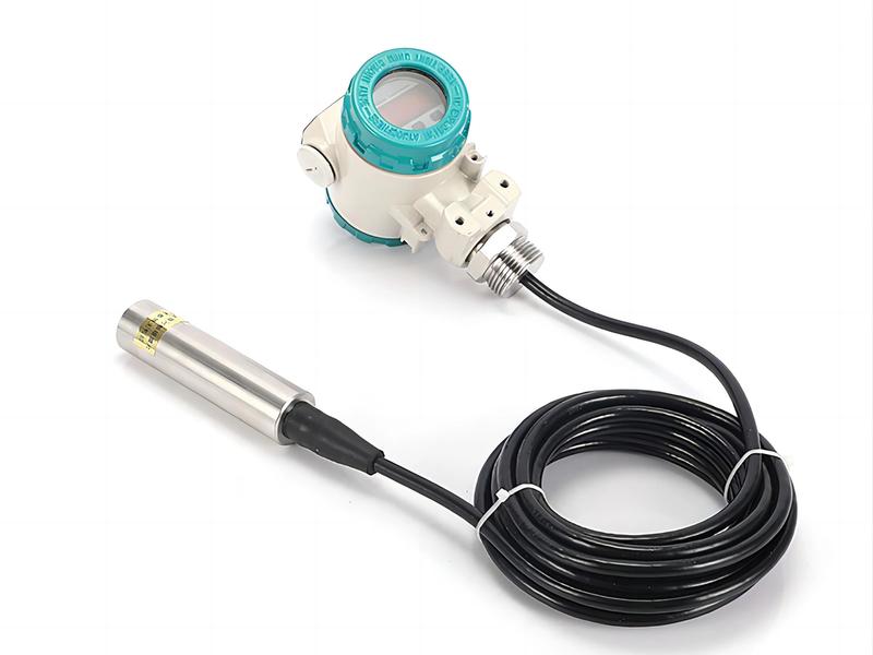
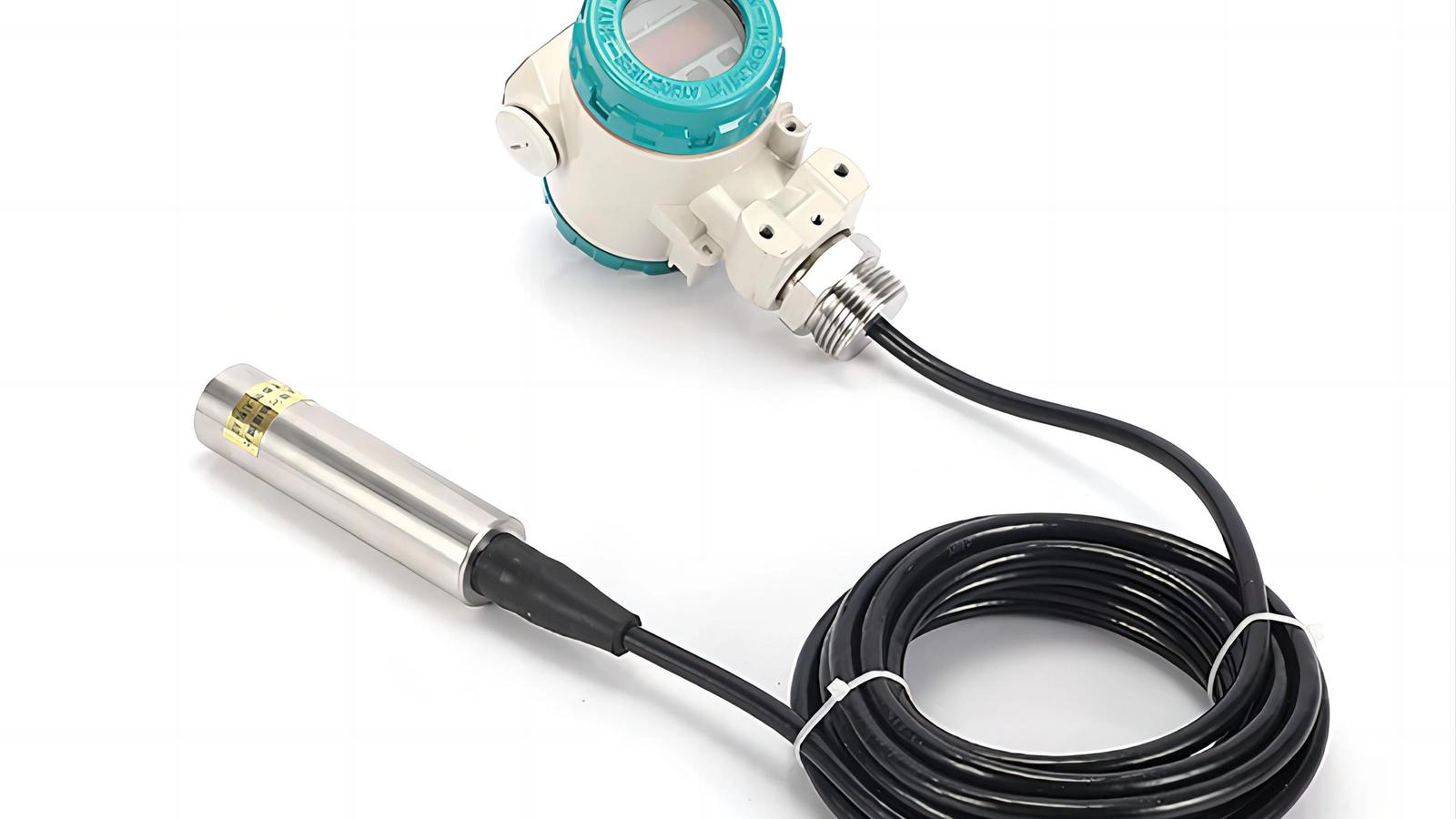
For most utilities, the submersible hydrostatic level transmitter is the default wet well level sensor: a pressure element suspended near the bottom senses hydrostatic head (about 9.81 kPa per meter of water) and outputs 4–20 mA/HART. Because it measures pressure below the surface, foam, vapor, and condensation cannot distort its reading — the failure modes that most often disable non-contact sensors. A 5 m-range unit at 0.25% FS resolves roughly ±12.5 mm, comfortably inside the 100–200 mm pump on/off band operators typically set to reduce motor cycling. Floats and pressure switches remain useful as redundant high-level alarms, but they are mechanical, foul faster, and drift more.
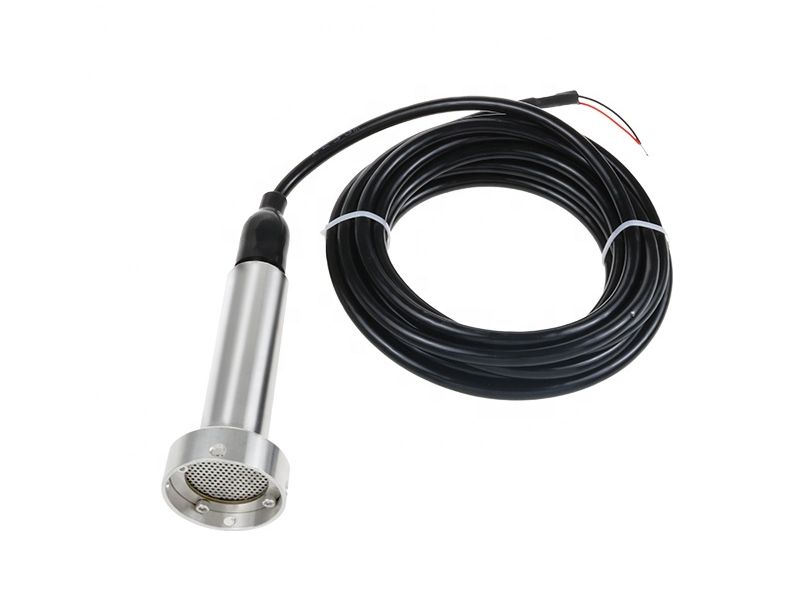
Where non-contact measurement is preferred — deep wells, heavy grease, or confined tops — an FMCW radar (60 or 80 GHz) measures from above and reads through most foam blankets at higher first cost. Ultrasonic works in cleaner lift stations when the transducer is protected from condensation, but it is the least robust choice in raw sewage. WELK offers submersible hydrostatic level transmitters for general duty and a dedicated wastewater hydrostatic level transmitter with sewage-duty cable and diaphragm options for lift station level control.
Open channel flow measurement derives discharge from liquid head upstream of a hydraulic structure — a Parshall or Palmer-Bowlus flume, or a V-notch, rectangular, or trapezoidal weir. The head-to-flow relationship is nonlinear and fixed by geometry: for a V-notch weir Q ∝ h^2.5, for a rectangular weir Q ∝ h^1.5, and flumes follow similar power laws. That exponent is the reason accuracy matters: a 3% head error produces roughly a 5–8% flow error, so small level errors translate into large metering errors.
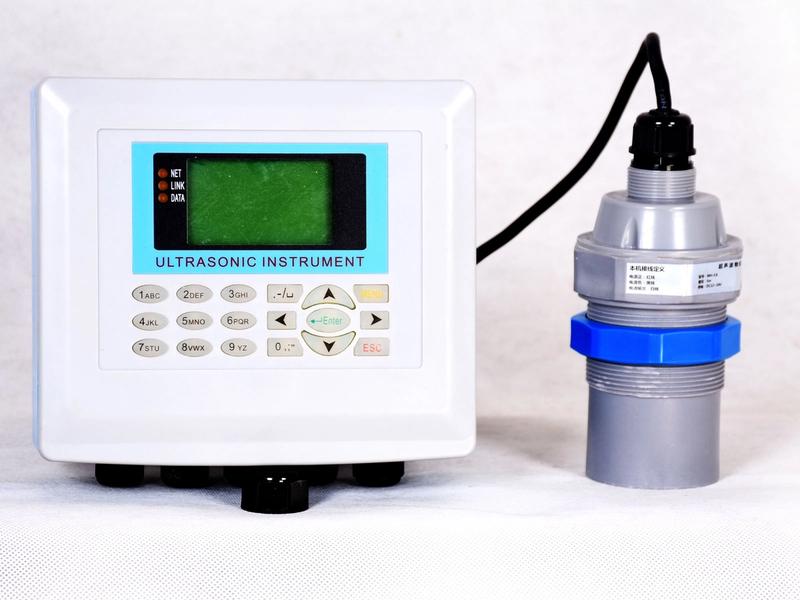
The practical requirement is a level sensor with small absolute error at low heads, mounted in a calm stilling location upstream of the throat, feeding a converter that applies the correct discharge equation (per ISO 4359 and ISO 4373). Ultrasonic is the traditional workhorse — non-contact, affordable, and commonly sold as a complete open channel ultrasonic flow meter with head-to-flow curves pre-programmed. FMCW radar is a growing upgrade where foam, fog, or frost disturb ultrasonic echoes, and it preserves the same mounting geometry. A submersible hydrostatic transmitter can also serve open-channel duty when mounted in a stilling well at a known elevation, converting head directly with total immunity to foam. Whichever technology is selected, verify the ±3–6 mm head accuracy against the structure's certified discharge table before commissioning.
Clarifiers and process tanks combine several distinct measurement problems. Weir-level on a clarifier is straightforward — radar or ultrasonic from above, or hydrostatic from below. Sludge blanket level, the interface between settled sludge and clear liquid, is a different measurement that needs an interface or density probe rather than a general-purpose level transmitter. Foam layers are common on aeration basins and clarifiers; through a foam blanket, only radar (which penetrates it) or a submerged hydrostatic element reports the true liquid level.
For dosing and sludge duty the media are viscous and coating — polymer, coagulant, lime slurry, primary sludge. A flush-diaphragm transmitter mounts flush with the tank wall so no dead pocket traps solids, and it handles pastes that would clog a protruding diaphragm; WELK's flush diaphragm hydrostatic level transmitter is the usual choice for such media. In mixing tanks, turbulence and vapor do not disturb hydrostatic or radar sensors, whereas ultrasonic scatters off surface turbulence and often requires a stilling well.
Elevated tanks, ground reservoirs, and drinking water storage typically span 10–30 m and feed inventory, leak detection, and level-limit alarms into SCADA. The dominant solution is a top-mounted FMCW radar: a 60 GHz water level radar sensor provides 0.1–0.3% FS accuracy with ±3 mm repeatability, a 0.05–0.15 m blind zone that is easy to design around, and no wetted moving parts — a decisive advantage on tall, hard-to-reach vessels. In standpipes and deep wells, a submersible hydrostatic transmitter stays competitive where a drop cable or stilling tube already exists. Potable service imposes material constraints — 316L stainless wetted parts, water-grade elastomers, hygienic finish — and any sensor on a pressurized tank must be rated for working pressure, not merely depth.
The table below compares the four main families on the numbers that actually decide wastewater projects. Accuracy is stated as a percentage of calibrated full span (FS) at reference conditions.
| Parameter | Submersible Hydrostatic | Ultrasonic | 60/80 GHz FMCW Radar | Float / Point Switch |
|---|---|---|---|---|
| Typical accuracy | 0.25–0.5% FS (0.1% premium) | ±0.2–0.5% FS or ±3–6 mm | 0.1–0.3% FS; ±3 mm | Switch point only; ±3–5 mm |
| Typical range | 0–1 m to 0–100 m+ WC | 0.3–10 m (to ~20 m special) | 0.2–30 m (to ~70 m special) | Contact (point level) |
| Foam tolerance | Excellent — senses below surface | Poor — foam absorbs pulse | Good — penetrates foam blankets | n/a |
| Condensation / vapor | Excellent | Poor–Fair — transducer wetting | Excellent | n/a |
| Dead band (blind zone) | None at top; must stay submerged | 0.2–0.5 m below transducer | 0.05–0.15 m below antenna | n/a |
| Maintenance | Periodic diaphragm and vent cleaning | Transducer cleaning; temperature compensation | Minimal — occasional lens wipe | Frequent mechanical cleaning |
| Relative cost | Low | Low–Medium | Medium–High | Very low |
| Technology | Best For | Main Limitation |
|---|---|---|
| Submersible hydrostatic | Foam-heavy wells; deep tanks; pressurized vessels | Must remain submerged; diaphragm can coat in sludge |
| Ultrasonic | Clean open channels and tanks; budget projects | Foam; condensation; and turbulence degrade the echo |
| FMCW radar | Foam; condensation; tall tanks; low-maintenance sites | Highest first cost; needs clear headroom for the dead band |
| Float / point switch | Redundant alarms; point-level interlocks | Point level only; mechanical parts foul and wear |
The price ranking runs float < ultrasonic < hydrostatic < radar, but total cost of ownership is what matters in a treatment plant. In raw wastewater, radar's higher first cost is typically repaid through lower labor and fewer callouts; a submersible level transmitter is the best value where the element can stay submerged and be cleaned on a schedule; ultrasonic remains economical where the site is clean and accessible. A useful heuristic: if foam can cover the surface, eliminate ultrasonic; if the vessel is deep and wet, hydrostatic and radar are the only robust choices.
Work through the list below in order; each step eliminates technologies before cost becomes the deciding factor.
Submersible hydrostatic transmitters:
Radar and ultrasonic transmitters:
Wiring and signal integrity:
Submersible hydrostatic transmitters are the most common and cost-effective choice: they ignore foam and condensation, need no top clearance, and typically deliver 0.25–0.5% FS. Where non-contact measurement is required, a 60/80 GHz radar is the strongest alternative; ultrasonic works in clean wells but is the least robust in raw sewage. Keep a float or switch as a redundant high-level alarm.
Standard units are ±0.25–0.5% of full scale — for a 5 m range, ±12.5–25 mm. Premium versions reach 0.1% FS. Accuracy is quoted against full span, so select a range close to the real working level for the tightest readings.
No. Foam absorbs and scatters the ultrasonic pulse, causing erratic or lost echo. Radar penetrates most foam blankets, and hydrostatic sensors are unaffected because they measure pressure below the surface. In foam-heavy wastewater, choose hydrostatic or radar.
A level sensor measures head upstream of a flume or weir, and the transmitter applies the structure's discharge equation — for a V-notch weir, Q ∝ h^2.5 — to compute flow. Because flow error amplifies level error, use the most accurate practical head measurement (±3–6 mm) and verify it against the structure's certified table per ISO 4359.
The blind zone is the dead band directly below the instrument where no measurement is possible. Ultrasonic transducers typically carry 0.2–0.5 m; 60 GHz radar 0.05–0.15 m. Design the installation so the highest liquid level never enters the blind zone. Hydrostatic transmitters have no upper dead zone, but the element must remain submerged.
Selection is only half the project — consistent quality and verifiable specifications are the other half. WELK manufactures submersible hydrostatic, ultrasonic, and radar level instruments in-house under an ISO 9001 quality system, with factory calibration and wetted materials verified before shipment. Submit an RFQ through the site with your range, media, output, and accuracy requirements, and the engineering team will confirm the configuration, cable, and mounting for your site. You can review WELK's factory quality control before you buy.
Submersible hydrostatic level transmitter for wells, reservoirs, tanks and water projects with cable length and output configured by depth.
Submersible hydrostatic transmitter configured for sewage pits, wet wells and wastewater tanks with anti-blocking diaphragm review.
Ultrasonic head-level measurement package for flumes, weirs, wastewater channels and industrial discharge flow monitoring.
Send drawings, dimensions, material, environment or operating conditions, and we will help confirm the right specification.
Uploaded reference files are included with the inquiry. For larger CAD packages, reply to the confirmation email or send them here:
Our team typically replies within 24 hours.