For process engineers and procurement managers specifying level instruments, the output signal decides how a transmitter communicates with a PLC or SCADA system, and the choice comes down to three practical options. 4-20 mA is the dominant analog standard: a two-wire loop-powered transmitter represents level as a current between 4 mA (empty) and 20 mA (full), a signal that is noise-immune, independent of cable resistance, and read by virtually every PLC analog input card in existence. HART (Highway Addressable Remote Transducer) keeps the 4-20 mA loop intact but superimposes a digital Frequency Shift Keying (FSK) signal at 1200 baud on the same two wires, so one cable pair carries both the analog level value and digital diagnostics, configuration data, and multiple process variables. Modbus RS-485 is a fully digital fieldbus: data travels as binary frames over a differential two-wire bus at rates from 9600 to 115.2 kbaud, supports up to 32 devices on a single segment, and reaches up to 1200 m (about 4000 ft) at 9600 baud. In short: choose 4-20 mA when you need the simplest, most universal, loop-powered analog signal; HART when you want digital diagnostics and remote configuration on the same two wires; and Modbus RS-485 when you are networking multiple instruments into a PLC/SCADA system and want multi-variable, multi-drop digital communication.
Why the Output Signal Matters for Level Instruments
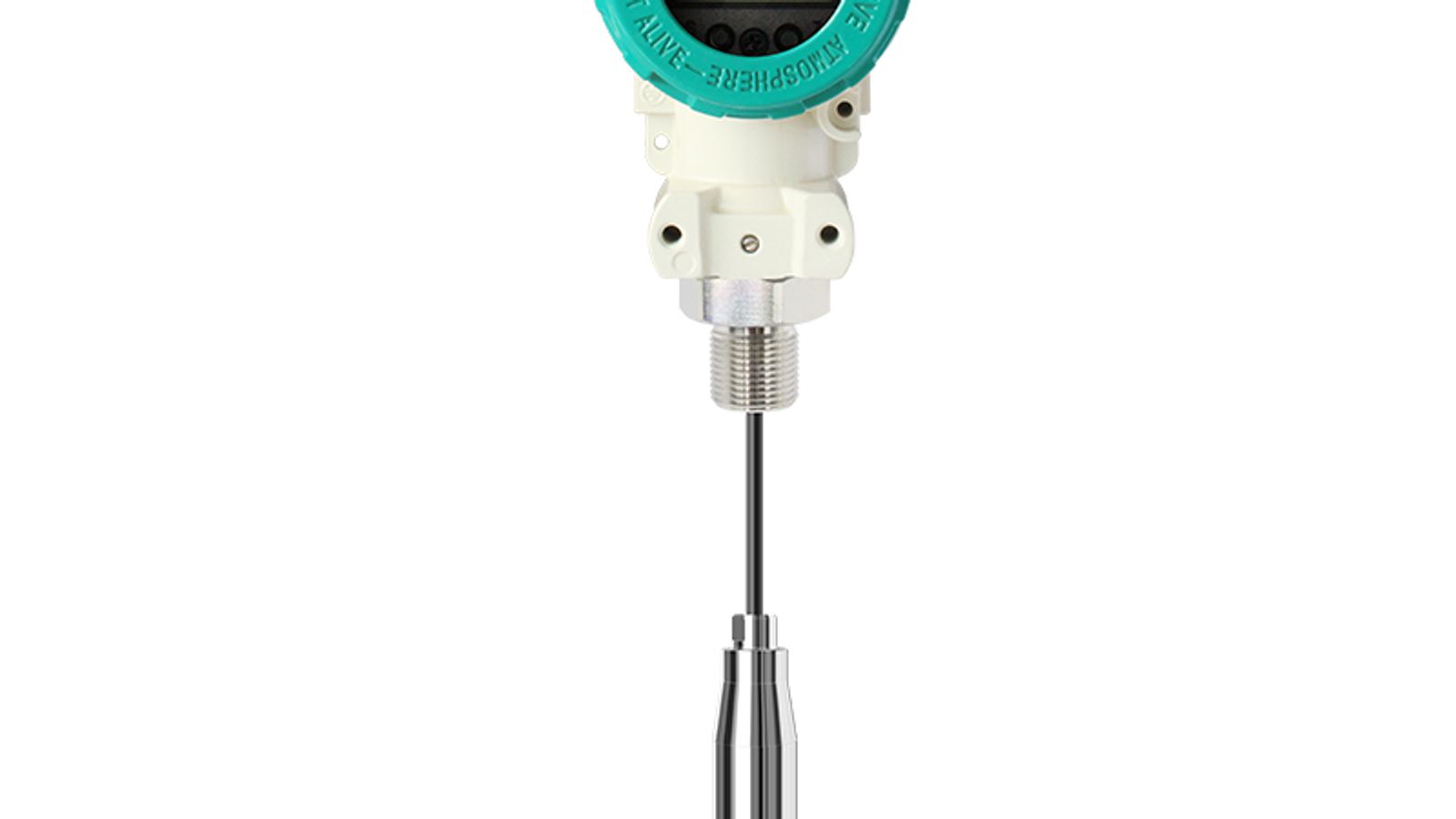
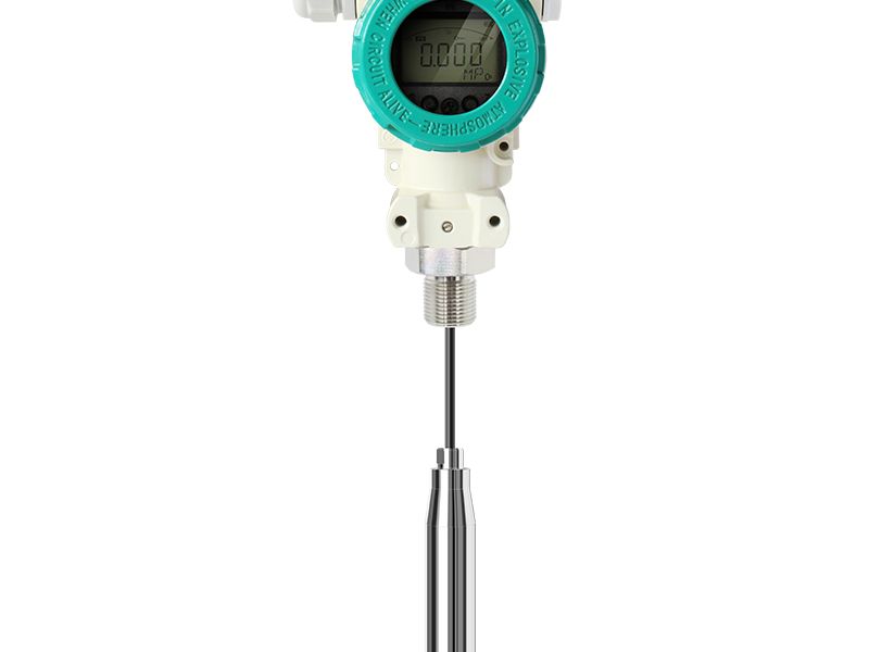
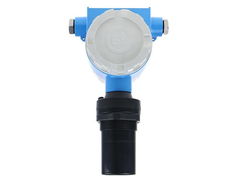
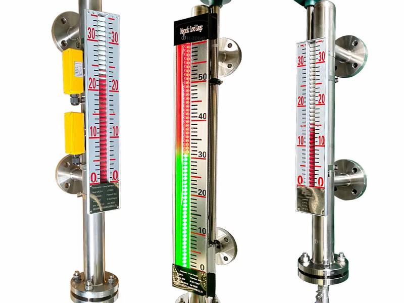
Level transmitters—radar, ultrasonic, hydrostatic, and magnetic float types—all do the same core job: convert a physical level into a standardized electrical signal. That signal is what your control system reads, and it determines everything downstream of the sensor: which analog input (AI) or communication card the instrument plugs into, how far away the instrument can be from the control room, how many variables you can extract, and how much each field device costs to commission.
Get the output wrong and you pay in engineering hours: fieldbus devices wired into analog-only systems sit unconfigured, while analog transmitters on multi-drop networks force you to install one cable per point. Get it right and the same measurement can feed a DCS loop, a SCADA historian, and an on-site indicator simultaneously. Three factors dominate the decision:
- Cable and infrastructure. Analog loops run over ordinary twisted pair and need only a 24 V DC supply and an AI card. RS-485 needs a master, termination resistors, and proper addressing. HART needs a modem or a multiplexer if your PLC lacks native HART support.
- Data richness. A raw 4-20 mA signal carries one number. HART carries that number plus diagnostics and up to four digital variables. RS-485 carries whatever registers the instrument publishes—level, distance, signal strength, temperature, and diagnostic flags.
- Network topology. One analog transmitter per cable pair. Up to 32 (or more with repeaters) RS-485 transmitters per bus. HART is essentially point-to-point, though multi-drop is possible in digital-only mode.
The rest of this article walks through each protocol in detail, compares them side by side, and gives a practical method for choosing the right output for your PLC/SCADA architecture.
4-20 mA Analog Loop: The Universal Baseline
How a Two-Wire 4-20 mA Loop Works
A two-wire loop-powered transmitter is wired in series with a DC supply (typically 24 V DC) and a load resistor inside the PLC analog input card. The transmitter regulates the current flowing through the loop so that it is proportional to the measured level: 4 mA at the low end of the range, 20 mA at the high end, linear in between. Because the same two wires carry both power and signal, no separate power supply cable is needed—the loop is self-powered.
The math that matters for installation is the loop-load calculation. The transmitter has a minimum working voltage (commonly 8 to 12 V DC) and draws a maximum of 20 mA. The maximum total loop resistance is the supply voltage minus the transmitter's minimum voltage, divided by 20 mA. With a 24 V supply and a 10 V minimum, that leaves 14 V for the loop, or 700 Ω of total resistance—enough for hundreds of meters of cable plus the PLC input resistor. This is why 4-20 mA is so forgiving: cable length is limited by loop resistance, not by a protocol-specific distance rule, and a 500+ m run is routine with a 24 V supply and standard instrument cable.
Failure behavior is standardized too. NAMUR NE43 defines out-of-range and fault states as 3.6 mA and 21 mA, so a broken sensor, a cut wire, or an electronics fault drives the loop outside the 4-20 mA measurement band, and the PLC can be programmed to raise an alarm instead of reading a false "empty" or "full" value. This single feature is a large part of why safety-conscious plants still default to 4-20 mA.
Strengths and Limits
The strengths are hard to argue with. A 4-20 mA output is read by every PLC and DCS on the market with zero protocol configuration. It is intrinsically safe when paired with an approved barrier, so it is the standard choice in hazardous-area level measurement. It is cheap to commission and easy to troubleshoot with nothing more than a multimeter. And because the current loop is immune to wire resistance and picks up very little interference, it is accurate over long runs.
The limits are equally clear. One cable pair carries exactly one measurement—level. Diagnostics are minimal or nonexistent on a bare analog transmitter, so you cannot remotely check sensor health, configuration, or echo quality. Range changes and zero/span adjustments usually require physical access to the device or a handheld programmer. And if your SCADA needs temperature, distance, or signal-strength data, an analog-only output simply cannot deliver it. For these reasons, 4-20 mA is best understood as the baseline, not the ceiling.
Practical applications are everywhere: two-wire ultrasonic level transmitters run on exactly this principle, as do magnetic float level transmitters with 4-20 mA output for simple tank gauging where a local indicator plus one analog value is all the operator needs.
HART Protocol: Digital Diagnostics on the Same Two Wires
How HART Works
HART was designed to solve a specific problem: add digital communication to the millions of installed 4-20 mA loops without rewiring anything. It uses the Bell 202 standard to superimpose a digital signal on the analog loop. The transmitter shifts a 1200 Hz tone to represent a logical "1" and a 2200 Hz tone to represent a "0," at a data rate of 1200 baud. Because the FSK tones are above the audio range and well above the 0-10 Hz bandwidth of the analog loop, the digital signal is invisible to the PLC's analog input and does not affect the 4-20 mA value.
The result is two simultaneous channels on one pair of wires: the analog channel carries the primary variable (level, as 4-20 mA), and the digital channel carries configuration, calibration, diagnostics, and device status. In practice this means an engineer with a HART modem or communicator can interrogate the transmitter from the control room or a junction box, read its health, change its range, and verify its echo quality—without climbing a tank.
Point-to-point is the default HART topology: one transmitter, one loop, one 4-20 mA primary variable. A HART device publishes multiple dynamic variables—the primary (PV), secondary, tertiary, and quaternary variables—so a single hydrostatic transmitter can report level as the analog signal while also carrying density-derived variables, process temperature, or raw pressure digitally. Newer HART versions (HART 6 and 7) support up to four dynamic variables and faster bursts, but the defining constraint remains: a 1200 baud link updates roughly twice per second, which is plenty for configuration and monitoring but far too slow for fast process control.
HART also offers a multi-drop mode in which up to 15 devices share one cable pair, each with a unique address. In multi-drop, the analog loop is disabled and all devices fix their output at 4 mA, communicating digitally only. Multi-drop is used sparingly because it gives up the analog signal, but it is a legitimate option for digital-only monitoring networks.
Strengths and Limits
The big advantage of HART is backward compatibility. It is the only technology that gives you digital diagnostics without giving up the analog signal, so it slots into existing 4-20 mA infrastructure with no PLC hardware changes—your analog input card keeps reading level, and a HART modem or multiplexer adds the digital channel on top. This makes HART the de facto retrofit standard for smart level transmitters.
The limits follow from the 1200 baud FSK link. Communication is slow, so HART is a configuration and maintenance protocol, not a high-throughput data highway. A single HART loop carries one primary analog value; getting all four dynamic variables digitally usually requires a multiplexer or a HART-aware PLC card. And because each device sits on its own loop, HART does not reduce cable count the way a fieldbus does.
Typical HART deployments in level measurement are smart hydrostatic level transmitters with HART on chemical and water tanks, where the operator wants a reliable 4-20 mA level into the DCS plus remote zero/span adjustment and diagnostics, and radar units where echo-quality data helps technicians confirm measurement integrity without entering the field.
Modbus RS-485: The Fully Digital Fieldbus
How the RS-485 Bus Works
RS-485 is a differential, multi-drop electrical standard—not a protocol by itself, but the physical layer that Modbus RTU runs on. Data is transmitted as a voltage difference between two wires (A and B), which gives excellent immunity to electrical noise and common-mode interference, a critical property in industrial plants full of variable-frequency drives and large motors. The bus is half-duplex: one pair of wires carries traffic in both directions, one device at a time, with the master polling each slave in turn.
The numbers engineers quote are the RS-485 limits. A single segment supports up to 32 unit loads—in practice, up to 32 transmitters. Maximum cable length is 1200 m at 9600 baud, decreasing as the baud rate rises; higher speeds shorten the usable distance. Repeaters extend both device count and distance, and bias and termination resistors at each end of the bus keep the signal clean. Because each device has a unique address (1 to 247 in Modbus), the master can poll every instrument on the bus and collect its data over one cable pair.
Modbus RTU frames are compact and deterministic: a master sends a request, the addressed slave responds, typically within milliseconds. Standard function codes read and write registers, and most level transmitters expose their data as 16-bit or 32-bit floating-point registers—level, distance, percentage, temperature, and diagnostic status all become plain numbers a PLC or SCADA can read directly. This is the defining difference from 4-20 mA and HART: the instrument publishes many variables, not one.
Strengths and Limits
The decisive advantages of Modbus RS-485 are multi-drop topology and multi-variable data. One cable into a tank farm can serve 32 transmitters, which collapses wiring, termination racks, and analog input density. The same bus that carries level also carries distance, signal strength, and self-diagnostics, so a SCADA historian gets a much richer data set without extra field wiring. Protocol overhead is low, the specification is open and royalty-free, and Modbus remains the most widely supported industrial serial protocol on earth—nearly every PLC, RTU, and protocol converter speaks it.
The limits are worth knowing before you commit. RS-485 is serial and half-duplex, so total throughput is shared across the bus; with 32 devices you must budget polling cycles, and a 9600 baud link supports only a few hundred register reads per second across the whole network. Wiring discipline matters: the bus needs a continuous daisy chain, proper termination at both ends, and correct addressing, and a single mis-wired device can take down the segment. Many PLCs also lack a native RS-485 port, so you may need a serial card, an RS-485-to-Ethernet converter, or a gateway—a real but modest cost. Finally, RS-485 is not intrinsically safe by itself; hazardous-area installations still require approved barriers and Ex-certified devices.
Where does Modbus RS-485 earn its keep in level measurement? On multi-tank sites. An 80 GHz radar level meter with RS-485 output can be one of dozens of slaves on a tank-farm bus feeding a control room, and wireless IoT radar level meters extend the same idea to remote wells and reservoirs where running cable is uneconomical. For high-density, high-value data collection, the fieldbus wins.
Side-by-Side Comparison Table
| Criterion | 4-20 mA Analog Loop | HART (FSK on 4-20 mA) | Modbus RS-485 (Digital Fieldbus) |
|---|
| Signal type | Analog current loop (4 mA = 0%; 20 mA = 100%) | Analog 4-20 mA + digital FSK superimposed at 1200 baud | Fully digital; differential RS-485; binary frames |
| Data rate | Continuous analog; no digital data | 1200 baud (~2 digital updates per second) | 9.6 to 115.2 kbaud; commonly 9600 |
| Max cable length | Loop-resistance limited; 500+ m typical with 24 V DC | Up to 3000 m on twisted pair (per HART spec) | 1200 m at 9600 baud; less at higher baud |
| Variables transmitted | 1 (level) | 1 analog + up to 4 digital dynamic variables | Many (level; distance; %; temperature; diagnostics via registers) |
| PLC/SCADA integration | Universal analog input card; zero configuration | Analog input card + HART modem or multiplexer | RS-485 port or converter; master addressing and polling |
| Typical level instrument use | Two-wire ultrasonic; magnetic float; basic radar | Smart hydrostatic and radar with remote config/diagnostics | Multi-drop radar and ultrasonic on tank farms and remote sites |
| Relative cost | Lowest | Low to moderate (modem/multiplexer extra) | Moderate (serial card; converter; or gateway extra) |
How to Choose the Right Output for PLC/SCADA Integration
There is no universal "best" output—there is the output that fits your existing infrastructure, your data needs, and your commissioning budget. Work through these questions in order.
1. What does your control system already have?
Inventory the free channels on your PLC or SCADA. If you have spare analog input cards and a 24 V DC distribution, 4-20 mA is the cheapest, fastest path to a live measurement—wire it, range it, and it works. If your PLC has native HART support or you already own HART multiplexers, HART devices give you diagnostics for nearly the same installation cost. If your plant standardized on RS-485 or you have a serial-to-Ethernet gateway feeding the SCADA, Modbus is the natural fit. Match the transmitter to the hardware you already paid for.
2. How many instruments share one cable route?
This is the economics driver. One transmitter on an isolated tank: 4-20 mA, and often the loop powers a local indicator at the same time. Ten tanks in a bunded area with one cable tray to the control room: Modbus RS-485 turns ten cable pairs into one bus, and the saved cable, gland, and termination costs usually exceed the price of the serial hardware. If you need diagnostics on the same wiring but are not ready for fieldbus, HART is the compromise that preserves your analog channels.
3. What data does your SCADA actually need?
If the answer is "one level number in a control loop," 4-20 mA is complete. If you need echo quality, signal strength, and temperature trends for predictive maintenance, HART delivers them over the existing loop, and RS-485 delivers them in bulk for every device on the bus. Data needs also decide baud rate: a few registers polled once a second run fine at 9600 baud, while a dense historian feed may justify 38.4 or 57.6 kbaud—always check the distance-vs-baud curve before you commit to a rate.
4. Hazardous area or not?
For intrinsic safety, 4-20 mA through an approved barrier is the most mature and widely certified approach. HART rides the same loop and inherits the same Ex approvals when the device is certified. RS-485 in a hazardous area demands Ex-certified devices and approved barriers or isolators, and multi-drop intrinsically safe bus design is more involved—plan for it early if your application is Zone 1 or Division 1. If you are unsure, the quality control and certification pages of your instrument supplier are the right place to check what each device actually holds.
5. What is the maintenance skill level on site?
An analog loop is diagnosed with a multimeter and understood by any technician. HART configuration requires a handheld communicator or a laptop with a HART modem. RS-485 troubleshooting requires a working knowledge of addressing, termination, and register maps. If your site has minimal instrumentation support, the simpler output is the more reliable one—a point worth weighing as heavily as the hardware price.
A word on hybrid and custom packages
You are not forced to pick one output for the whole plant. Many level transmitter display and controller packages combine a local indicator with 4-20 mA out and an optional RS-485 link, so the same measurement serves a local operator and the central SCADA simultaneously. Where you have a mix of tank sizes, a pragmatic design is 4-20 mA on critical control loops, HART on important but non-critical tanks where diagnostics matter, and RS-485 on the dense tank farm. Applications like chemical storage tanks and water and wastewater basins tend to follow exactly this pattern.
FAQ
Can a level transmitter output both 4-20 mA and Modbus RS-485?
Yes. Many industrial level transmitters are dual-output, providing a 4-20 mA analog signal for the DCS control loop and an RS-485 Modbus link for configuration, diagnostics, and multi-variable data. Specify both outputs if you want local analog control plus remote digital visibility.
Is HART the same as 4-20 mA?
HART is built on top of 4-20 mA. The loop still carries a standard 4-20 mA analog signal, and HART superimposes a 1200 baud FSK digital signal on the same two wires. So a HART transmitter is fully backward-compatible with an analog 4-20 mA input; you simply lose the digital channel if your system has no HART modem.
How far can a Modbus RS-485 level transmitter be from the PLC?
Up to 1200 m (about 4000 ft) at 9600 baud on a single segment. The maximum distance decreases as baud rate increases, and adding repeaters extends both distance and the number of devices (up to 32 per segment without repeaters).
How many devices can share one RS-485 bus?
Up to 32 transmitters per segment on standard RS-485. Repeaters allow additional segments, and each device needs a unique Modbus address (1 to 247) so the master can poll it individually.
Does HART support multiple devices on one pair of wires?
Yes, in multi-drop mode up to 15 HART devices can share one cable pair, but the analog loop is then disabled and devices communicate digitally only. The standard point-to-point HART installation is one transmitter per loop, which keeps the 4-20 mA signal active.
Is Modbus RS-485 intrinsically safe?
RS-485 itself is not intrinsically safe; it must be installed through approved safety barriers and the devices must carry Ex certification for hazardous-area use. For classified areas, a loop-powered 4-20 mA transmitter through a certified barrier remains the most straightforward choice.
Get the Right Output the First Time
The output signal is decided once, at specification time, and its consequences last for the life of the instrument. If you are still weighing 4-20 mA against HART or Modbus RS-485 for your tanks, pumps, or process vessels, the fastest way to settle it is to talk to an instrumentation engineer who knows all three—and who sells them. WELK is a Chinese manufacturer of radar, ultrasonic, hydrostatic, and magnetic level instruments, and our engineers size the output to your PLC/SCADA, not the other way around. For more background on how instrument families compare, see our radar vs ultrasonic level meter guide, or review how we select and qualify suppliers if this is your first sourcing project. Contact WELK today with your tank dimensions, control system model, and cable runs, and get a free quote plus a concrete output-signal recommendation before you buy.